 |
|
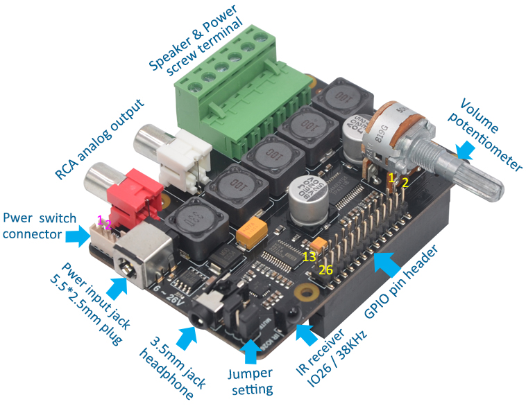
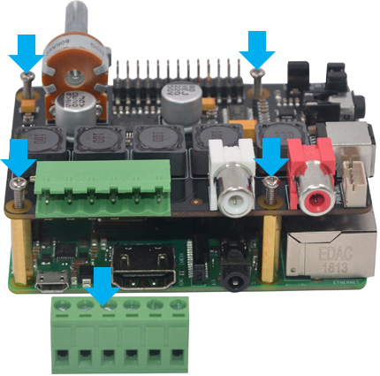
| ❷ |
a) Remove the plug
from terminal block connector
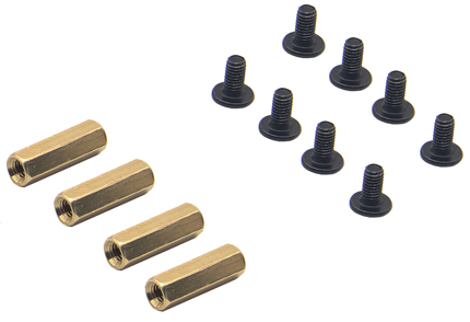
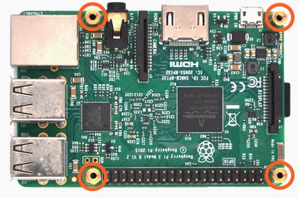
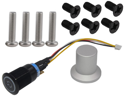
b) Push a screws
(M2.5*28mm) up through
the mounting hole
on the topside of the X400.
C) Screw the spacer (M2.5*20mm)
down
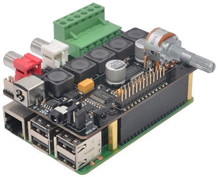
d) Plugs the X400 board
straight into your Raspberry Pi B+'s
GPIO header and
screw down
(M2.5*28mm) |
|
| |
|
|
|
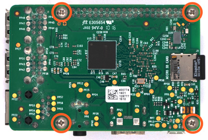
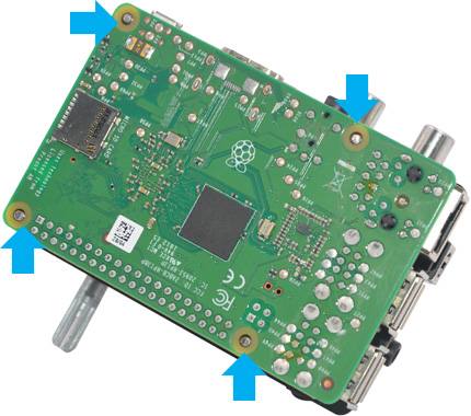
❸ |
The four screws
(M2.5*28mm) not
screwed over the
Raspberry Pi B+'s PCB |
|
|
|
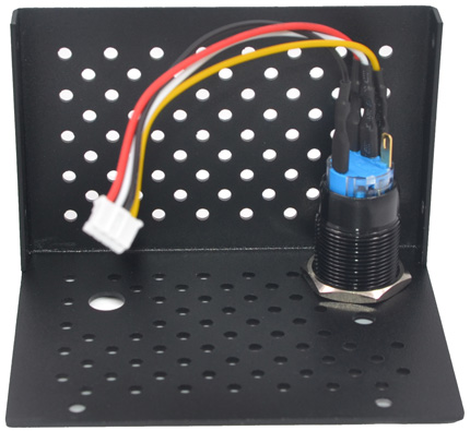
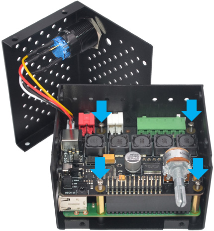
❹ |
Unscrew the nut from
power switch and mount it to top cover |
|
 |
|
 |
| |
|
|
|
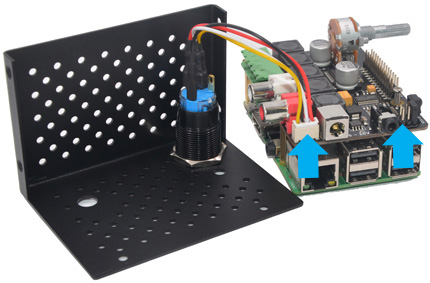
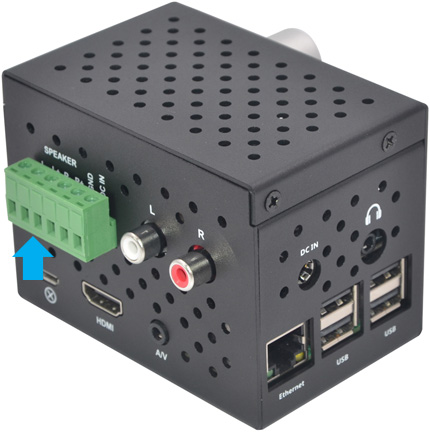
❺ |
a) Insert the connector
of power switch into the X400 as arrowed below.
b) Remove the jumper link for "PWR" |
|
|
|
❻ |
Mount the board assembly onto the bottom case and screw
down. |
|
|
|
 |
| |
|
|
|
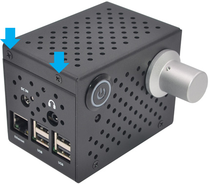
❼ |
a) Snap the top cover
and bottom case together.
b) Screw the top cover down
(M3*5mm) |
 |
|
|
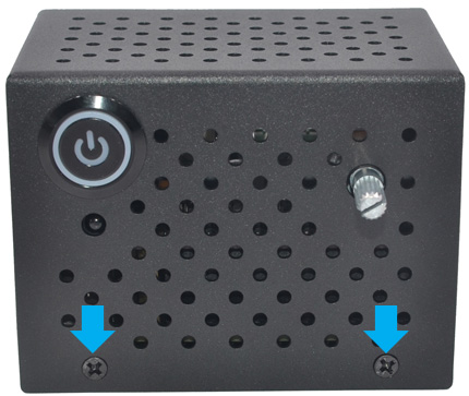
❽ |
Screw the top cover down
(M3*5mm) |
 |
| |
|
|
|
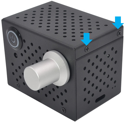
❾ |
Screw the top cover down
(M3*5mm) |
 |
|
|
❿ |
Insert the volume knob
into the handle of potentiometer and fix with an
1.5mm hex key |
 |
| |
|
|
|
⓫ |
Insert the plug into
the SPK & Power terminal block |
 |
|
|
| |
|
|