|
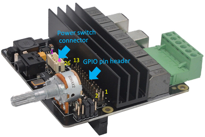
Pin No. |
Pin Description |
|
1 |
Power on/off control connecting to switch |
|
2 |
Power on/off control connecting to switch |
|
3 |
GND
connecting to LED - |
|
4 |
5Vdc
connecting to LED + |
1. Latching power
switch should be used.
2. Jumper for "PWR" should be removed if using external switch.
3. Connector - Pitch 2.0mm 4pos |
|
|
Jumper Name |
Usage |
|
Mute |
Short
- Speaker mute disabled |
Open
- Speaker mute controlled by GPIO22
GPIO22 high - Mute disabled
GPIO22 low - Mute enabled (no sound) |
|
AMP |
Short
- 60W amplifier in shutdown mode |
| Open
- 60W amplifier in working mode |
|
PWR |
Short
- Power on when power applied |
Open - Using an external power switch to
control power
on /off |
|