|
|
|
|
Home
Products
Web
Store
Product
Customization
OEM/ODM
Contact |
|
|
|
|
|
|
|
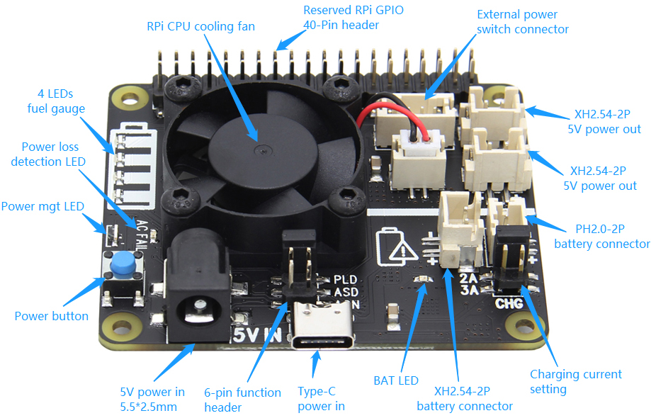
Function Description |
X708
|
|
|
|
|
|
|
|
 |
|
|
|
|
|
|
|
| ❶ |
Power Jack and
Connectors |
|
|
|
|
Power input |
5Vdc +/- 5% ,
≥3A |
|
DC Power Plug Size |
5.5*2.5mm |
|
USB power in socket |
Type-C |
|
UPS power output |
5.1Vdc
8A |
|
Power output connector |
XH2.54mm 2pin |
1. X708 powers the
Raspberry Pi via the 40-pin header (Pin 2 & 4)
2. Don't power the Raspberry Pi via the Pi's type-C USB socket
3. X708 can be powered via the onboard DC jack
or
Type-C USB
power socket |
|
|
Jumper Name |
Usage |
PLD
(Power loss detection)
Pin 1&2 |
Short
- AC Power loss or power adapter failure
detection
enabled
(Active if power adapter disconnected) |
| Open
- Power loss detection disabled |
AON
(Auto power-on)
Pin 3&4 |
Short
- Auto power-on when power applied
(Will delay 3 seconds before
powering on) |
| Open
-
Auto power-on disabled |
ASD
(Auto shutdown)
Pin 5&6 |
Short
- Automatic shutdown enabled when
battery
low (≤3Vdc )
Procedure to enable ASD
function --IMPORTANT
1. Battery voltage
must be >3Vdc
2. Insert the battery into the holder
3. Wait 3 seconds then insert the jumper
4. If the jumper inserted before battery, remove
battery & jumper then repeat step 1, 2 and 3. |
| Open
- Automatic shutdown disabled |
|
|
|
|
|
|
❸ |
Connector for
External Power Switch |
|
|
|
❹ |
Power button
(Script for power mgnt installed) |
|
|
Pin No. |
Pin Description |
|
1 |
Power on/off control connecting to switch |
|
2 |
Ground |
|
3 |
LED+
for battery low indicator |
|
4 |
LED+
for power on, rebooting and shutdown |
1. Please use
momentary switch only and don't use latching switch
2. Connector - Pitch 2.0mm 4pos |
|
|
Press and Release |
Raspberry
Pi and X708 turn on |
|
Press and hold for 1~2 seconds |
System
rebooting |
|
Press and hold for 3~7 seconds |
System shutting down |
|
Press and hold for >8 seconds |
Force
shutdown |
|
|
|
|
|
|
|
|
|
❻ |
Fuel
gauge - LED Indicator |
|
|
LED Name |
Usage |
BAT
LOW |
LED
red on indicates battery low (≤3.0Vdc) or
blue power button pressed
(Jumper for ASD inserted) |
5V
OUT |
LED green on flashing indicates 5V power out
and UPS powered by battery |
AC
FAIL |
LED
red on indicates AC power loss or PSU
failure or PSU disconnected |
|
PWR |
LED
blue indicates
Stays on - Power on
Blinks rapidly - system rebooting
Blinks slowly - Shutting down |
|
|
Operation of Discharging
|
Capacity C (%) |
D1 |
D2 |
D3 |
D4 |
|
C ≥75% |
ON |
ON |
ON |
ON |
|
50%≤C<75% |
ON |
ON |
ON |
OFF |
|
25%≤C<50% |
ON |
ON |
OFF |
OFF |
|
3%≤C<25% |
ON |
OFF |
OFF |
OFF |
|
0%<C<3% |
Flashing |
OFF |
OFF |
OFF |
Operation
of charging
|
Capacity C (%) |
D1 |
D2 |
D3 |
D4 |
|
Fully charged |
ON |
ON |
ON |
ON |
|
75%≤C |
ON |
ON |
ON |
Flashing |
|
50%≤C<75% |
ON |
ON |
Flashing |
OFF |
|
25%≤C<50% |
ON |
Flashing |
OFF |
OFF |
|
C<25% |
Flashing |
OFF |
OFF |
OFF |
|
|
|
|
|
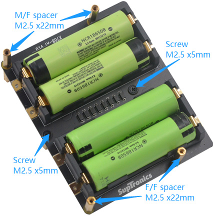
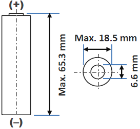
❽ |
18650 battery dimension |
|
|
Pin No. |
Usage |
|
2, 4 |
+5V
power supply |
|
3, 5 |
I2C for
RTC and battery
fuel-gauge systems |
|
6 |
Ground |
|
29 |
GPIO5
for power management |
|
32 |
GPIO12
for power management |
|
33 |
GPIO13
for power management |
|
31 |
GPIO6
for AC power loss detection
(Jumper for PLD inserted, High=power loss,
Low=Power supply normal) |
|
|
 |
|
|
|
|
|
|
|
|
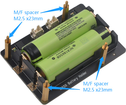
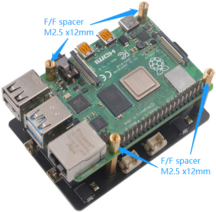
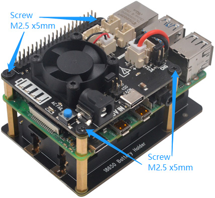
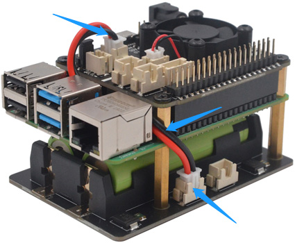
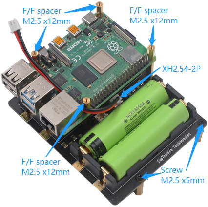
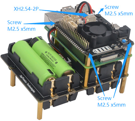
Board Assembly |
|
|
|
|
|
|
|
FOR USE WITH 2-CELL BATTERY HOLDAER
|
|
|
|
|
|
|
|
|
|
|
|
FOR USE WITH 8-CELL BATTERY HOLDAER
|
|
|
|
|
|
|
|
|
|
|
|
|
|
|
|
|
|
|
|
© 2018
SUPTRONICS TECHNOLOGIES LIMITED, ALL RIGHTS RESEVERED |
|
|
|
|
|