|
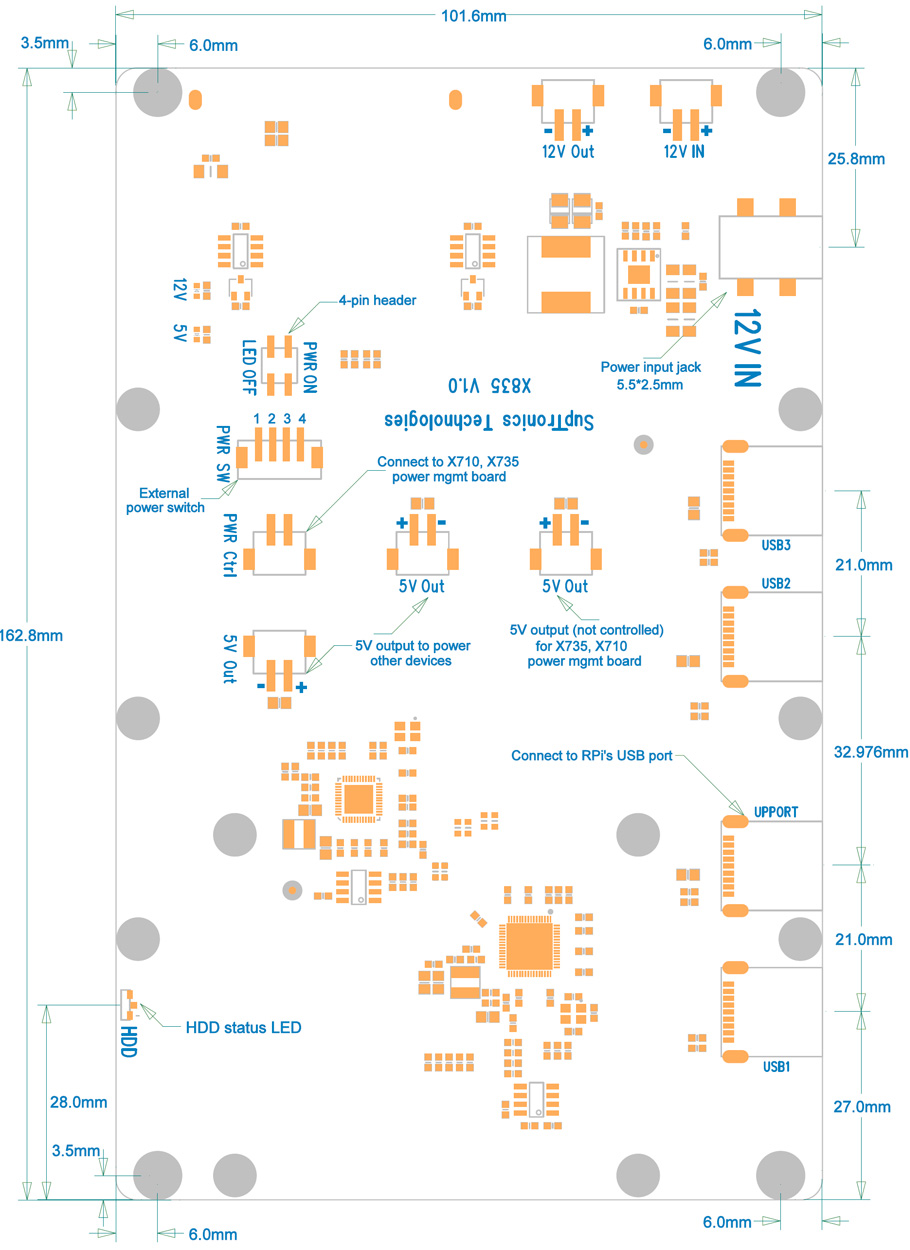
❶ |
Push a
screws
(M2.5*5mm)
up through the mounting hole
on the underside of the X835 and screw the spacer
(M2.5*12mm)
down until it is hand tight. |
 |
|
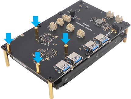
| ❷ |
Insert your 3.5" hard disk
into the SATA socket on the PCB bottom side. |

|
| |
|
|
|
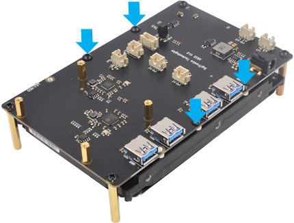
❸ |
Using four M3*8mm screws
to secure the hard drive. |
|
|
|
❹ |
Push a screw
(M3*8mm) up through
the mounting hole on the topside of the X835 and
screw the spacer (M3*32mm)
down until it is hand tight. |
|
 |
|
 |
| |
|
|
|
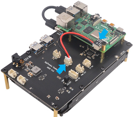
❺ |
a)Place your Raspberry
Pi on top of X835 and screw down.
b)Plugs the power daughter board straight
into your
Raspberry Pi B+'s GPIO header.
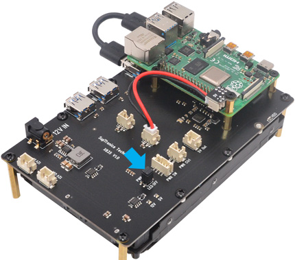
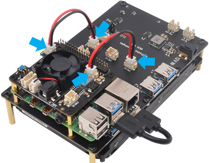
c)Plugs in the 2-pin power cable into the "5V'
female sockets
on the power daughter board and X835 |
|
|
|
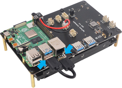
❻ |
Plug in the USB male-to-male cable into the Rpi's USB3.0
port and the "UPPORT" on the X835. |
|
 |
|
 |
| |
|
|
|
❼ |
Optional -To use with
X735 /
X710 power mgmt board
a)Unscrew 4 screws and
spacer on the topside of Rpi
b)Screw the M2.5*12 M/F spacer down
until it is hand tight
c)Remove the jumper socket fitted for "PWR'. |
|
|
|
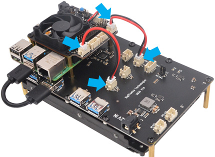
❽ |
a)Plugs
the X735 straight into your Raspberry Pi's GPIO
header and screw down (M2.5*5mm screws)
b) Plug in the 2-pin power cable into the
female JST
connectors on X735 and X835.
Power
adapter must be connected to the X835 only , not
Raspberry Pi and X735. |
|
 |
|
 |
|
|
|
|
|
❾ |
a)Plugs
the X710 straight into your Raspberry Pi's GPIO
header and screw down (M2.5*5mm screws)
b) Plug in the 2-pin power cable into the
female JST
connectors on X710 and X835.
Power
adapter must be connected to the X835 only , not
Raspberry Pi and X710. |
|
|
|
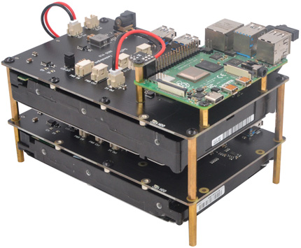
❿ |
Optional - X835 is
stackable and supports multiple HDDs working at the same
time
Push a screw
(M3*8mm) up through
the mounting hole on the topside of the first X835 and screw the
spacer (M3*40mm)
down until it is hand tight. |
|
 |
|
|
|
|
|
|
|
⓫ |
Push the second X835 up through
the M/F M3*40 spacers on the underside of the first X835 and
screw down (Spacer
F/F M3*32mm, if add one more
X835 then using a spacer M/F M3 x40mm) until it is hand tight. |
|
|
|
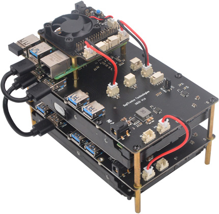
⓬ |
a)
Connect the USB3 cable from "USB1" port on the first
X835
to the "UPPORT" on the second X835.
b) Connect the 2-pin power cable from "12V out" JST
connector on the first X835 to the "12V in" JST connector
on the second X835.
Power
adapter must be connected to the first X835 |
|
 |
|
 |