|
Installing the Raspberry Pi Compute
Module 5 |
|
Step 1
Protecting from ESD |
 |
|
Grounding protects the
components from the static electricity that
can be naturally present (electrostatic
discharge, ESD).
|
 |
|
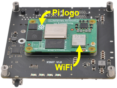
Step 2
Aligh the IO
board and CM5 |
 |
|
|
|
|
|
|
|
|
|
|
|
|
|
|
|
|
|
|
- Confirm the Compute Module
is correctly mated by looking at
each corner of the IO Board.
|
|
|
|
|
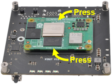
Step 3
Installing
the CM5 |
 |
|
|
|
|
|
|
|
|
|
-
This
requires quite a bit of force.
If you don't hear a loud click,
it is most likely not fully
seated.
-
Do a visual
check to make sure the CM5 is
installed correctly: it needs to
run parallel to the IO board.
|
|
|
|
|
|
CAUTION!
Do not press on any chipsets, as
this may damage your CM5. |
|
|
|
|
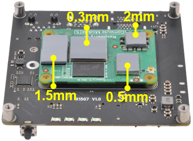
Step 4
Use silicone
thermal pads for optimal heat dissipation |
 |
|
|
|
|
|
|
-
Inspect
for Debris: Dust, oil,
or residue can interfere with
heat transfer, so make sure both
surfaces are spotless.
|
|
|
- RP1 and
Ethernet IC: 1.5mm (LxW, 12x20.6mm)
- CPU: 0.3mm
(LxW, 17x17mm)
- PMIC: 2mm
(LxW, 10x10mm)
- WiFi module:
0.5mm (LxW, 13x10mm)
CAUTION! Using
incorrect pad thickness may damage
your CM5.
|
|
|
|
|
|
|
|
|
|
|
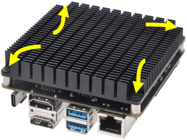
Step 5
Installing the heat sink |
 |
|
|
|
|
|
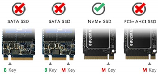
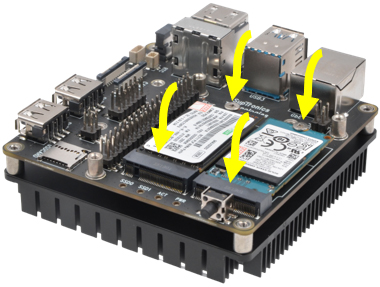
Step 6
Installing the M.2 2242 NVMe SSD devices |
 |
|
|
|
|