|
|
|
| |
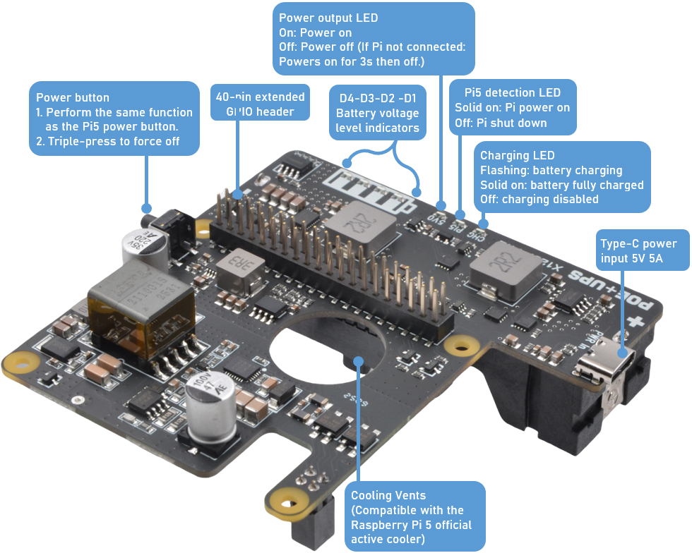
Hardware description |
|
| |
|
| |
1 |
|
Raspberry Pi
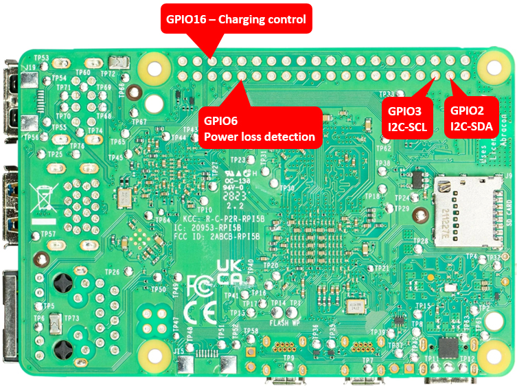
GPIO used |
|
| |
|
|
|
PIN# |
GPIO |
Functions |
|
3 |
GPIO2 |
I2C-SDA,
battery fuel-gauge systems -reading
battery voltage and percentage |
|
5 |
GPIO3 |
I2C-SCL,
battery fuel-gauge systems -reading
battery voltage and percentage |
|
31 |
GPIO6 |
AC power loss
& power adapter failture detection,
Low-power supply failed, High-power
supply OK |
|
36 |
GPIO16 |
Control
battery charging, High-charging
disabled, Low-charging enabled |
|
|
| |
|
|
|
|
| |
|
|
 |
|
| |
|
|
|
|
| |
2 |
|
Battery voltage
level indicators |
|
| |
|
|
|
Battery voltage range (V) |
D1 |
D2 |
D3 |
D4 |
Remark |
|
3.87-4.2 |
ON |
ON |
ON |
ON |
discharging levels of 100% |
|
3.7-3.87 |
ON |
ON |
ON |
OFF |
discharging levels of 75% |
|
3.55-3.7 |
ON |
ON |
OFF |
OFF |
discharging levels of 50% |
|
3.4-3.55 |
ON |
OFF |
OFF |
OFF |
discharging levels of 25% |
|
Below 3.4 |
OFF |
OFF |
OFF |
OFF |
low battery |
|
|
|
|
|
|
|
| |
| |
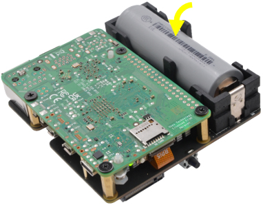
1 |
|
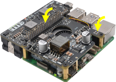
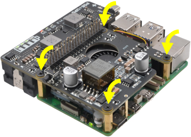
X1207 POE-powered UPS HAT
|
|
2 |
|
Raspberry Pi 5
|
|
| |
3 |
|
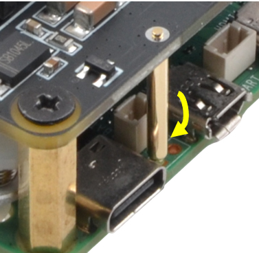
Power Supply USB-C 5V 5A |
|
4 |
|
micro-SD card (≥16GB) x1 |
|
|
| |
5 |
|
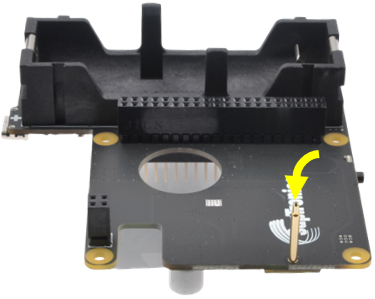
21700 4.2V rechargeable lithium-ion battery x1 |
|
|
|
|
|
| |
|
|
| |
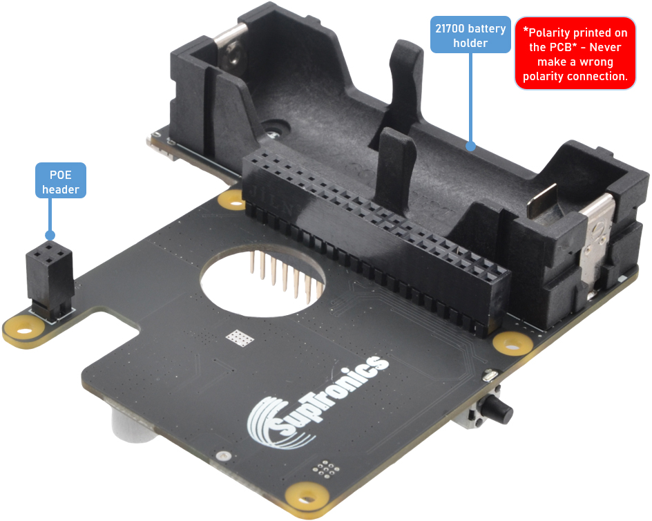
*
To ensure reliable operation, you must use a power
source that meets the minimum specification: either
an 802.3at (PoE+) switch or a 5V/5A USB-C power
adapter. An insufficient power supply will prevent
the system from starting and may result in a failure
to charge the battery.
|
|
|
| |
|
|
| |
|
|