|
|
|
|
|
| |
| |
1 |
|
RJ45 connector for ATX
control - pin description |
|
| |
|
|
|
Functions |
Name |
PIN# |
PIN# |
Name |
Functions |
|
Connect to PC reset switch |
RESET-SW |
1 |
2 |
RESET-SW |
Connect to PC reset
switch |
|
Connect to PC HDD LED- |
HDD LED- |
3 |
4 |
PWR-SW |
Connect to PC power
switch |
|
Connect to PC power switch |
PWR-SW |
5 |
6 |
HDD LED+ |
Connect to PC HDD LED+ |
|
Connect to PC power LED- |
PWR-LED- |
7 |
8 |
PWR-LED+ |
Connect to PC power
LED+ |
|
|
|
| |
|
|
| |
| |
1 |
|
X630-A3 IPKVM Kit x1
|
|
2 |
|
Raspberry Pi 4 Model B
|
|
|
| |
3 |
|
16GB micro-SD card x1
|
|
4 |
|
CR1220 coin battery x1 (For
Real-time clock)
|
|
|
| |
5 |
|
HDMI cable A Male to A Male x4 (For
HDMI video input)
|
|
6 |
|
Ethernet cable x1 (Connect to
your network)
|
|
| |
7 |
|
X630-A5 ATX control PCI card
(Optional, To control PC system power, system reset,
read status of HDD LED and power LED)
|
|
8 |
|
Ethernet cable x1 (Optional, for
use with X630-A5) |
|
|
|
|
|
|
|
|
|
|
| |
|
|
| |
|
|
| |
|
|
|
|
 |
| |
| |
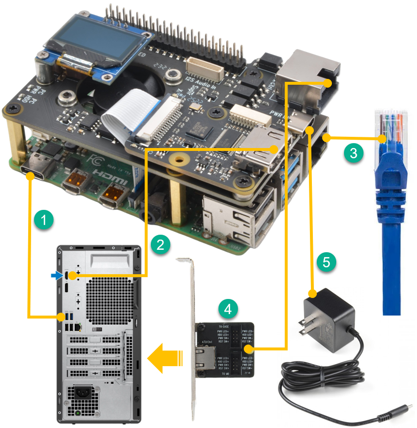
1 |
|
Locat a USB port on your
PC/server and connect to Raspberry Pi using the
supplied USB-C to USB-A cable
|
|
2 |
|
Locat a HDMI port on your
PC/server and connect using a HDMI cable A Male to A Male
|
|
|
|
|
|
|
|
|
| |
3 |
|
Connect to your network using an
Ethernet cable |
|
4 |
|
Connect to the X630-A3 ATX
control PCI card using an Ethernet cale - Optional,
install inside the chassis
|
|
|
|
|
|
|
|
|
| |
5 |
|
Connect to an USB Type-C power
supply (5V ≥3A) |
|
|
|
|
|
|
|
|

