|
|
|
|
|
| |
| |
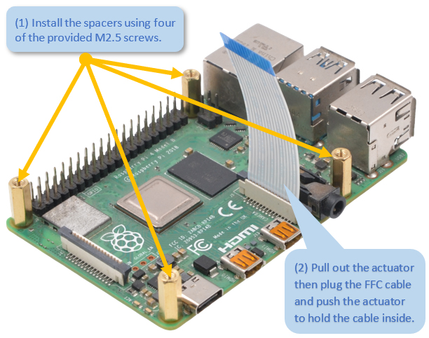
1 |
|
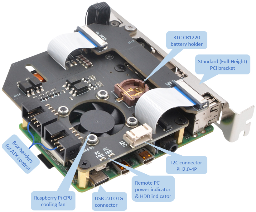
ATX control box header
- pin description |
|
| |
|
|
|
Functions |
Name |
PIN# |
PIN# |
Name |
Functions |
|
Control PC system reboot |
RST- |
1 |
2 |
RST+ |
Control PC system
reboot |
|
Control PC system power |
PWR- |
3 |
4 |
PWR+ |
Control PC system power |
|
Read the status of PC power LED |
HLED- |
5 |
6 |
HLED+ |
Read the status of PC
power LED |
|
Read the status of PC HDD LED |
PLED- |
7 |
8 |
PLED+ |
Read the status of PC
HDD LED |
|
|
|
| |
|
|
| |
| |
1 |
|
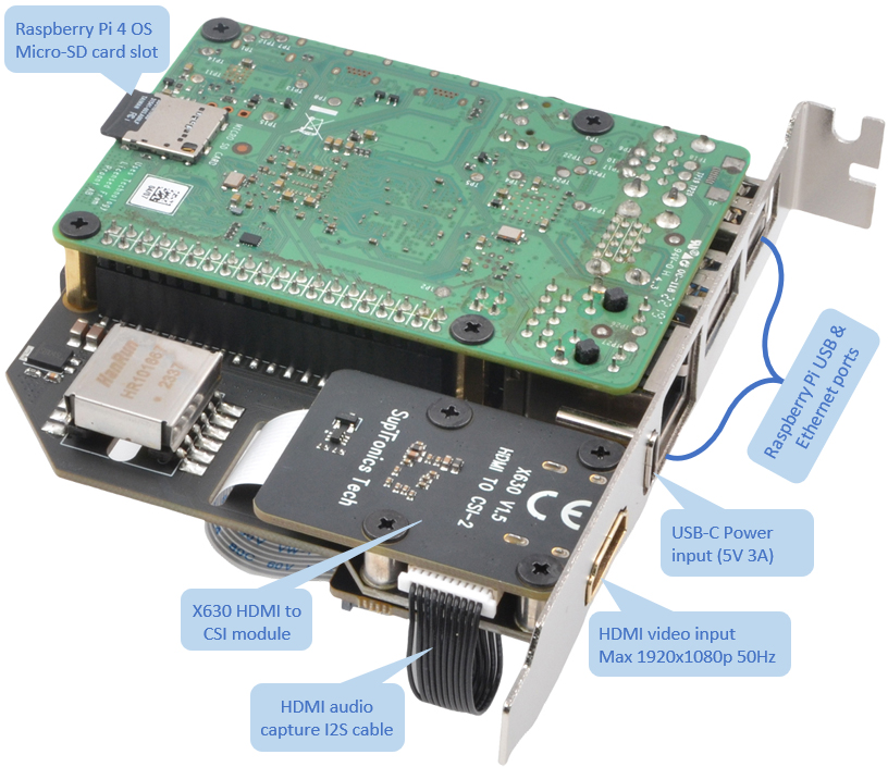
X630-A8 IPKVM PCI manageemnt card
x1
|
|
2 |
|
Raspberry Pi Compute Module 4 x1
(all variants Compatible)
|
|
|
| |
3 |
|
16GB micro-SD card x1
|
|
4 |
|
CR1220 coin battery x1 (For
Real-time clock)
|
|
|
| |
5 |
|
USB Type-C power supply (5V ≥
3A) x1 (Not required if Power over Ethernet).
|
|
6 |
|
HDMI Male to Male Cable x1
|
|
|
|
|
|
|
|
|
|
| |
|
|
| |
 |
| |
|
|
 |
| |
| |
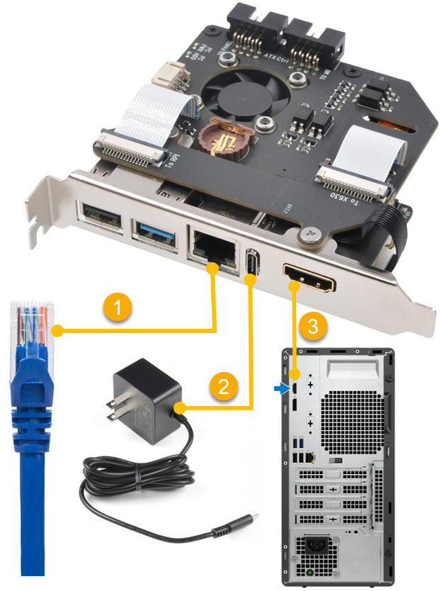
1 |
|
Connect to your network using an
Ethernet cable
|
|
2 |
|
Connect the USB-C power
supply (DC5V 3A),
not required if powering over Ethernet
|
|
| |
|
|
|
|
|
|
| |
3 |
|
Locat a HDMI port on your
PC/server and connect using a miniHDMI to HDMI cable
|
|
|
|
|
|
| |
|
|
|
|
|
|
|
|
|
|
 |
|
|
| |
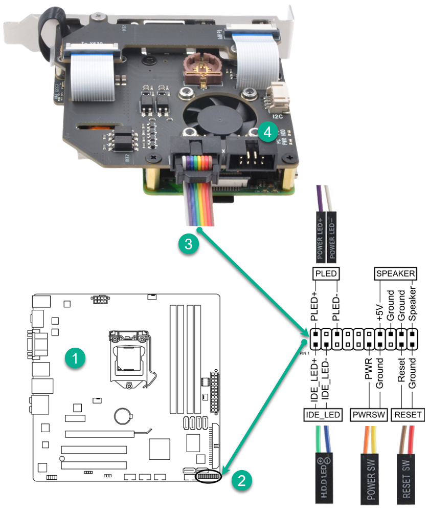
1 |
|
PC /server motherboard
|
|
2 |
|
Motherboard system panel
connector
|
|
|
|
|
|
|
|
|
|
|
| |
3 |
|
Plugs the ATX cable into
the box header and connects to motherboard system
panel header. |
|
4 |
|
Optional - Connect the Power
Switch wires, Reset Switch wires, HDD LED wires and
Power LED wires from front panel chassis connector
to the X650 box header (pinout printed on the board
bottom).
|
|
|
|
|
|
|
|
|
| |
|
|
Important Notes
1. The pin assignments for the panel header may
differ by model. Refer to the motherboard user's
manual for the actual pin assignments.
2. HDD LED and Power LED need proper polarity
connection to funciton. Check your motherboard
manual for polarity requirements.
|
|
| |
| |
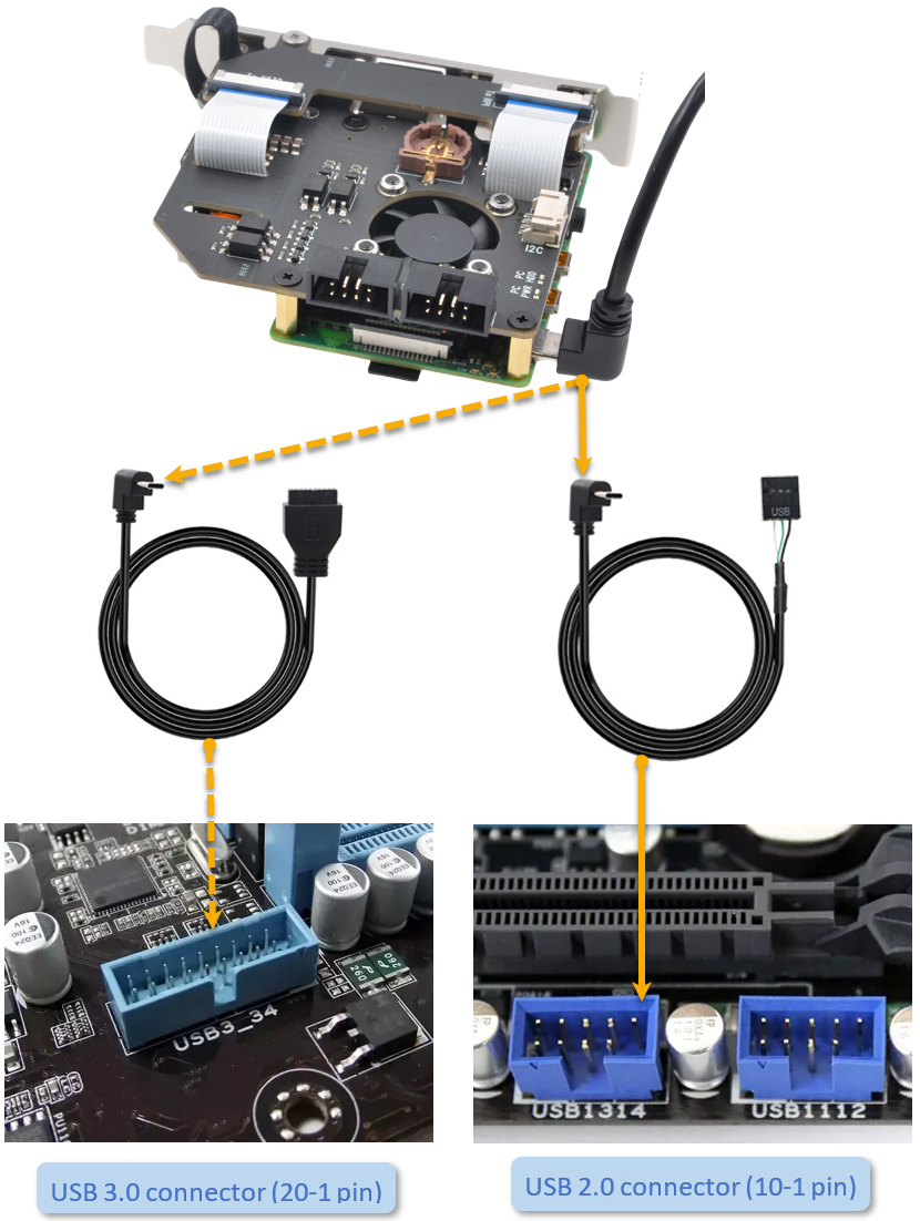
5 |
|
USB2.0 OTG cable
connection |
|
|
 |
| |
| |
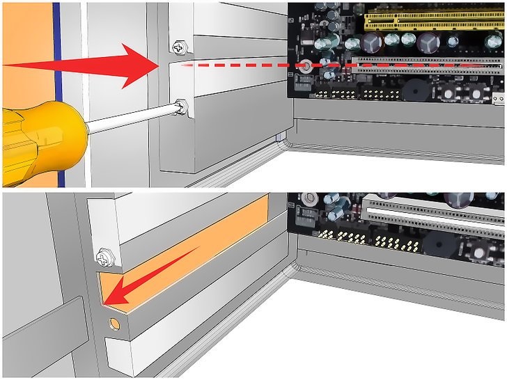
How to install the PCI card |
|
|
| |
| |
1 |
|
Unplug your computer.
Power down your computer and then unplug the power
cable and all the other cables that are connected to
the back.
|
|
| |
|
|
| |
2 |
|
Open your computer.
PCI cards need to be installed inside your Computer's
chassis. |
|
| |
|
|
|
|
| |
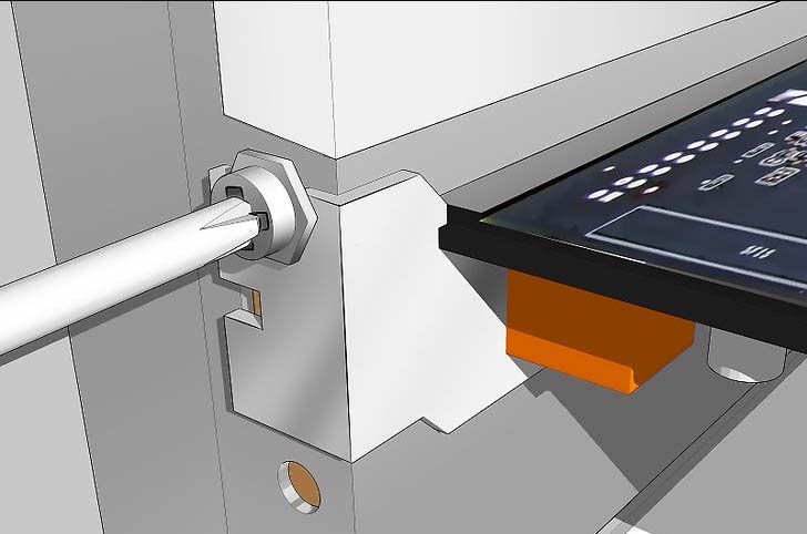
3 |
|
Remove the metal bay
cover. Each PCI slot will have a bay
associated with it on the back of the computer. When
there's nothing installed, the bays are covered by
small metal protectors. You can remove one by
unscrewing the single screw holding it in place and
then lifting it directly out of the case. Set the
screw aside.
|
|
|
|
|
|
| |
|
|
 |
|
| |
|
|
|
|
| |
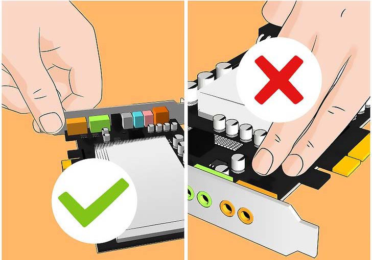
4 |
|
Gripping the PCI card by
the sides. Do not touch the contacts along the
bottom, and try to avoid touching any of the
circuitry.
|
|
|
|
|
|
| |
|
|
 |
|
| |
|
|
|
|
| |
5 |
|
Insert the card
and press it firmly straight down into the slot.
Ensure that the card is level and seated fully in
the slot before continuing. note that the X650 PCI
card is not required to insert into PCI slot on the
motherboard.
|
|
|
|
|
|
| |
|
|
|
|
| |
6 |
|
Secure the card.
Use the screw that you removed from the metal bay
cover and use it to secure the card into the same
hole. Tighten the screw firmly but not so tightly
that it will strip later.
|
|
|
|
|
|
| |
|
|
 |
|
| |
|
|
|
|
|