|
|
|
|
|
| |
| |
1 |
|
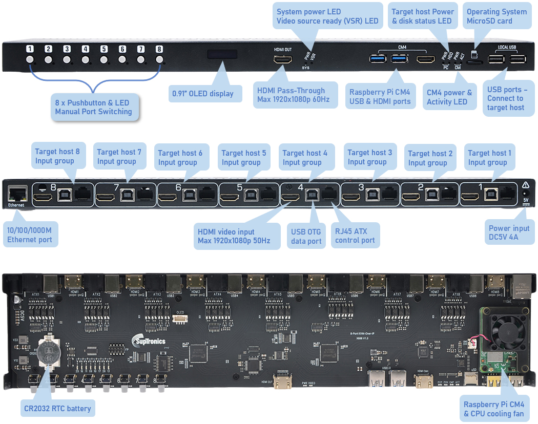
System Status LED
indiciators |
|
| |
|
|
|
LED name |
State |
LED Color |
Description |
|
SYS-PWR |
Solid on |
Blue |
5V System
power and 3.3V SSD power supply OK |
|
Blink |
Blue |
SSD data
reading /writing |
|
CM-PWR |
Solid on |
Red |
Indicates
that 5V power has been provided to the
compute module 4 (CM4) |
|
CM-ACT |
Blink |
Green |
Indicate the CM4 SD
card status and program activity |
|
PC-HDD |
Blink |
Green |
Reads the
status of PC HDD LED, indicates data reading
/writing |
|
PC-PWR |
Solid on |
Red |
Reads the
status of PC power LED, indicates PC power
supply OK |
|
VST |
Solid on |
Green |
HDMI input
video ready for streaming |
|
|
| |
|
|
|
|
|
| |
|
|
| |
|
|
| |
1 |
|
X688 8-port IPKVM switch DIY Kit x1
|
|
2 |
|
Raspberry Pi Compute Module4
without eMMC x1
|
|
|
| |
3 |
|
≥16GB micro-SD card x1
|
|
4 |
|
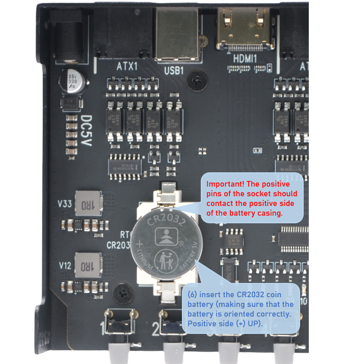
CR2032 coin battery x1 (For
Real-time clock)
|
|
|
| |
5 |
|
HDMI cable A Male to A Male x8 (For
HDMI video input)
|
|
6 |
|
Ethernet cable x1 (Connect to your network)
|
|
|
| |
|
For ATX power control
(Optional, To control PC system
power, system reset, read status of HDD LED and power LED) |
| |
7 |
|
X630-A5 ATX control PCI card
x1-8
|
|
8 |
|
RJ45 Ethernet cable x1-8
|
|
|
| |
|
For local operation |
| |
9 |
|
HDMI cable A Male to A Male x1
|
|
10 |
|
USB keyboard and mouse x1
|
|
|
| |
|
|
| |
|
| |
|
|
|
|
 |
| |
| |
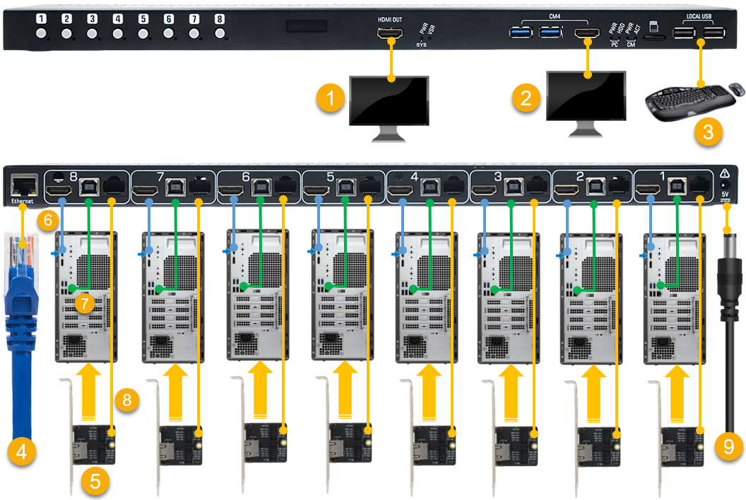
1 |
|
Connect the monitor for local
operation using a HDMI cable
A Male to A Male– The HDMI pass-through transmits both
video and audio signals from your target host. |
|
2 |
|
Optional for IPKVM
operating system setting & debug -
Connect the monitor for
CM4 HDMI
video output using a HDMI cable A Male to A Male |
|
|
|
|
|
|
|
|
| |
3 |
|
Connect the keyboard and mouse
for local operation of your target host.
|
|
4 |
|
Connect to your network using a RJ45 Ethernet cable |
|
| |
|
|
|
|
|
|
| |
5 |
|
Optional - Install the
X630-A5 ATX PCI card inside the chassis
for ATX power control |
|
6 |
|
Locat a HDMI port on your target host and connect
using a HDMI cable A Male to A Male |
|
| |
7 |
|
Locat a USB-A port on your
target host and connect to USB OTG port
using the supplied USB-A to USB-B cable
|
|
8 |
|
Connect to the X630-A5 ATX
control PCI card using a RJ45 Ethernet cale
|
|
| |
|
|
|
|
|
|
| |
9 |
|
Connect the power supply (DC5V
4A) |
|
10 |
|
Repeat steps 5, 6, 7, and 8 for
configuring target hosts 1-7
|
|
| |
|
|
|
|
|
|
|
|
|
|